渲染管线
最近回顾了一下基础的图形学内容,发现很多都忘记了,现在认真的总结一下。主要内容都来自d3d的官方文档当中提取的图形管线当中。
下图是一个总览的流程,这个流程主要是针对D3D API可配置的阶段:
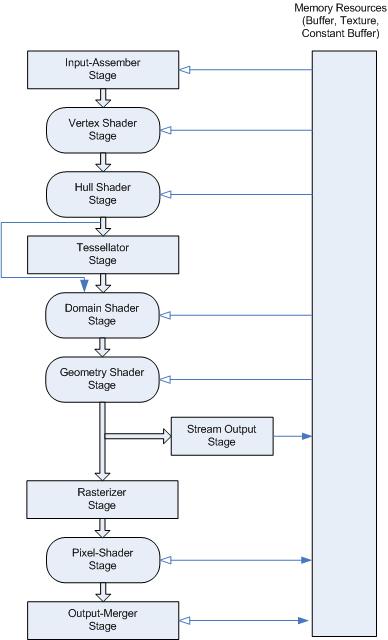
渲染管线总览
D3D 10和更高级的API支持将渲染管线 划分成不同的功能阶段,下面是每一个阶段的主要描述:
| Topic | Description |
|---|---|
| Input-Assembler Stage 输入装配阶段 | the first stage in the pipeline is the input-assembler (IA) stage.第一个阶段是输入装配阶段。 |
| Vertex Shader Stage | The vertex-shader (VS) stage processes vertices from the input assembler, performing per-vertex operations such as transformations, skinning, morphing, and per-vertex lighting. (vertexShder阶段主要处理逐顶点操作,包括:transformation,顶点光照,变形,蒙皮等,他的数据来源于IA阶段。)Vertex shaders always operate on a single input vertex and produce a single output vertex(输入输出都是单独顶点). |
| Tessellation Stages | 曲面细分,处理的是表面:三角形。 |
| Geometry Shader Stage | 处理一系列顶点输入,产生一系列顶点输出。 |
| Stream-Output Stage | The purpose of the stream-output stage is to continuously output (or stream) vertex data from the geometry-shader stage (or the vertex-shader stage if the geometry-shader stage is inactive) to one or more buffers in memory (see Getting Started with the Stream-Output Stage). 将顶点处理的数据传送到一个或者多个内存? |
| Rasterizer Stage | The rasterization stage converts vector information (composed of shapes or primitives) into a raster image (composed of pixels) for the purpose of displaying real-time 3D graphics. 从顶点到图像。 |
| Pixel Shader Stage | The pixel-shader stage (PS) enables rich shading techniques such as per-pixel lighting and post-processing. A pixel shader is a program that combines constant variables, texture data, interpolated per-vertex values, and other data to produce per-pixel outputs. (pixel Shader主要将常量、纹理数据、逐顶点插值数据等内容来生成像素输出)The rasterizer stage invokes a pixel shader once for each pixel covered by a primitive, however, it is possible to specify a NULL shader to avoid running a shader. (光栅化阶段会为每一个被图元覆盖的像素执行一次pixelShader) |
| Output-Merger Stage | The output-merger (OM) stage generates the final rendered pixel color using a combination of pipeline state(OM阶段会根据渲染状态的组合生成最终的颜色:pixel Shader输出,渲染目标,深度/stencil buffer内容), the pixel data generated by the pixel shaders, the contents of the render targets, and the contents of the depth/stencil buffers. The OM stage is the final step for determining which pixels are visible (with depth-stencil testing) and blending the final pixel colors.(OM阶段决定哪个像素可见,深度和stencil测试和blend。) |
渲染阶段
Input-Assembler Stage(IA) (未补全)
简介:IA阶段的目的主要是从user-filled buffer当中读取图元数据(points, lines and/or triangles),然后组合成在之后阶段需要使用的新的结构的图元数据。 AI阶段能够将顶点组合成不同的图元类型,组合过程需要读取相邻的数据,这部分数据只在Geometry Stage阶段可以。例如:如果一个几何着色器在三角形上被调用,那么他的输入就包括他自身的三个顶点,和相邻三角形的顶点数据。
IA阶段步骤总结
- Create Input Buffers:使用输入的vertex data初始化input buffer。
- Create the Input-Layout Object:使用input layout object描述vertex buffer中的数据类型。
- Bind Objects to the Input-Assembler Stage:将vertex data buffer和layout object 绑定到IA阶段。
- Specify the Primitive Type:定义顶点数据如何组成图元。
- Call Draw Methods:调用绘制方法,将绑定到IA的数据传送到pipeline。
Create Input Buffers
inpute buffer有两种:vertex buffer和index buffer。vertex buffer提供数据,index buffer提供数据索引,可以创建多个vertex buffer。可以创建一个index buffer。
Vertex Shader Stage
vertex Shader的输入最多为16 个 32-bit的4维向量,输出也是一样。一个vertex shader必须至少有一个输入和一个输出(一个标量)。
vertex Shader能够处理两个来自IA阶段的系统生成值:VertexID and InstanceID,他们只提供给vertex shader stage。
vertex Shader在所有顶点上运行,包括有邻接拓扑关系的图元的相邻顶点。
顶点着色器可以在不需要屏幕空间导数的情况下执行加载和纹理采样操作。(应该指的是类似Unity的Sample2D_Load操作)
Tessellation Stages(未补全)
Geometry Shader Stage
这部分没有太多特殊的内容,见官方文档。
Stream-Output Stage
连续的将顶点数据输出到内存的buffer当中。
When a triangle or line strip is bound to the input-assembler stage, each strip is converted into a list before they are streamed out。(所有的数据在输出之前,都是一个链表)The amount of data streamed out can vary(数据可以变化,例如:几何着色器会向链表插入数据,几何、纹理、常量数据在整个渲染流程中如何存储需要研究一下)。
Rasterizer Stage
将图元数据转化成光栅图像(像素),每个像素根据顶点进行插值。
光栅化阶段包括:视椎体剪裁、透视变化(剪裁空间坐标除z(这里说的不是z分量,而是深度值,对应的是剪裁空间坐标中的w分量))等。(Rasterization includes clipping vertices to the view frustum, performing a divide by z to provide perspective, mapping primitives to a 2D viewport, and determining how to invoke the pixel shader. )
重点:为什么不一步变换到NDC呢?因为,视椎体剪裁需要在Clip-Space进行。当完成视椎体剪裁之后,才会进行透视变化,这个时候才会进行透视除法。以上两步都在光栅化阶段进行。所以Unity在Vertex Shader阶段输出的是Clip-Space坐标,是提供给这个阶段使用的。
进入光栅化阶段的顶点,被认为是在齐次坐标的剪裁空间的(x,y,z ,w),x正方向向右,Y正方向向上,Z正方向是摄像机前方。(Vertices (x,y,z,w), coming into the rasterizer stage are assumed to be in homogeneous clip-space. In this coordinate space the X axis points right, Y points up and Z points away from camera.)
齐次坐标和NDC:
 [x y z w]   →   [x/w y/w z/w]
homogeneous     normalized device
clip space      coordinates (NDC)
Zbuffer优化:On hardware that implements hierarchical Z-buffer optimizations, you may enable preloading the z-buffer by setting the pixel shader stage to NULL while enabling depth and stencil testing.
Pixel Shader Stage
在这个阶段进行丰富的着色、光照和后处理计算。这个阶段使用常量、纹理数据、插值数据和其他顶点程序输出的数据。光栅化阶段会为每一个被图元覆盖的区域执行一次Pixel Shader。
Use the depth-write-enable state (in the output-merger stage) to control whether depth data gets written to a depth buffer (or use the discard instruction to discard data for that pixel). A pixel shader can also output an optional 32-bit, 1-component, floating-point, depth value for depth testing (using the SV_Depth semantic). The depth value is output in the oDepth register, and replaces the interpolated depth value for depth testing (assuming depth testing is enabled). There is no way to dynamically change between using fixed-function depth or shader oDepth。比较重要的部分是可以通过SV_Depth 语义来直接输出深度到深度贴图当中,这样可以直接代替来自Vertex Data的深度插值数据。不过这两种方式不能动态变化。目前没有在Unity当中尝试过。
Output-Merger Stage
OM阶段会根据渲染状态的组合生成最终的颜色:pixel Shader输出,渲染目标,深度/stencil buffer内容。
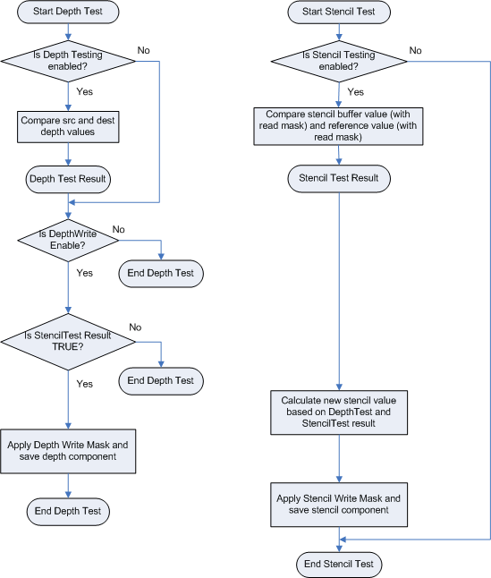
Depth-Stencil
OM阶段的第一步就是Depth-Stencil Testing,这步骤依赖于一张Depth-Stencil buffer。Depth-Stencil是作为纹理资源创建的,他包括了深度信息和Stencil信息。
深度信息用来决定哪些像素距离摄像机更近,Stencil数据用来当做Mask使用。他们在这个阶段使用用来决定这个像素是否被绘制。下图描述了Depth-Stencil是如何被使用的。
Depth-Stencil的状态如果没有被配置,那么久会使用默认参数。如果没有开启multisampling那么混合操作逐像素进行,如果开启,混合就在多个采样结果上进行。(这个内容我理解的是MSAA之类的操作)。
使用深度缓冲区来确定应该绘制哪个像素的过程称为depth-buffer,有时也称为z-buffer。
Blending
Blending的作用就是将一个或者多个像素颜色值混合作为最终的颜色输出。
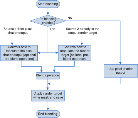
D3D文档里面说:Blend values (including BlendFactor) are always clamped to the range of the render-target format before blending. 。就是说所有混合的值会再blending阶段进行Clamp,但是我发现Unity如果使用负数的Alpha(Blend Factor)时并没有被Clamp
另一个要点:When you use sRGB render targets, the runtime converts the render target color into linear space before it performs blending. The runtime converts the final blended value back into sRGB space before it saves the value back to the render target. 当使用sRGB的render targets的时候,在混合之前会转换到线性空间,混合结束之后再返回sRGB的render target。Unity当中的做法是只使用Linear的render targets。全部渲染完成之后再一次性转换会原始的sRGB。
Multiple RenderTargets
多个渲染目标。一个Pixel Shader能够同时渲染8个render target。所有的render target需要是同一种类型(buffer, Texture1D, Texture1DArray, and so on),同一种尺寸 (width, height, depth, array size, sample counts)。但是可以有不同的数据格式(Each render target may have a different data format.)。例如:多个G-buffer在一个Pass完成,但根据存储数据的不同,使用了不同的数据格式。
Output-Write Mask
Use an output-write mask to control (per component) what data can be written to a render target.
这个没有在Unity当中找到对应物。
Sample Mask
这个没有在Unity当中找到对应物。